Sunday, 6 October 2013

Days 11 - 12: Last Weekend Overtime

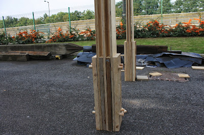
This weekend has been very tough on us since the workshop is closed and we had no resources to finish the project. Nevertheless, we payed from our own budget to get drills, jigsaw, dowels, hammers and everything else required to make it happen. We started by cutting the dowels for the base which consists of 2 pieces on the X axis of the post and 2 pieces on the Y axis interlocked together with dowels and locks to prevent the structure from tilting against wind forces or any kind of misuse.

Cutting the dowels inside AVA since this is the only place with power available
We used our own materials and ingenuity to clamp the last pieces together and drill the holes on the dowels for the locks, which are basically smaller dowels wedged in the bigger interlocks.

Clamping the post for maximum tension and cutting the holes on the dowels for the locks

Cutting the holes manually with our own drill

Base brace on the X axis

Base brace on X and Y axis
Our working conditions were so difficult to cope with that we even had to charge our drill batteries several times in order to keep working.

Charging our drill batteries in the AVA and in the West building later on when AVA closed
We had to make some modifications and last minute changes to make everything happen even though night was already upon us. The lights of the nearby highway gave us just enough light to work and eventually managed to finish the whole structure in one day. It is strong enough for Amir to have his late night workout.

Working out last minute changes

The structure is strong enough for Amir to do his workout on it

Elevation in perspective

Our final structure 

Friday, 4 October 2013

Day 10: The Twin Towers

Having all the pieces already cut yesterday made our lives much easier today. We started early by assembling the pieces together and the first frame was pretty much easy to lift and make it stand on its own balance.
Assembling the post by interlocking the panels with dowels
Lifting up our fully operational module for the first time

A free - standing frame
One problem we encountered while having it stand on its own weight proved out to be the wind speed. The location that we use as construction space is very much exposed to the high speed eastern winds and as a result our module started moving on one axis due to aerodynamics. It made us think however that a base is way more important than we thought it would be and we started coming up with different kind of designs to strengthen the base and reduce the tilting of the frame due to the wind.

High speed wind: A major problem at the moment

First concept for the base with interlocking pieces

We thought of a base which consists of 2 pieces that interlock with each other in a manner that they can only be taken apart vertically. (which is not possible due to the weight of the post) Apart from taking much time to mark and make the 2 pieces interlock perfectly, it seems that we didn't think of the pressure forced on the interlock and eventually ended up with a scrap wood and a failed idea.

By dividing the load of work to all group members we made great progress and managed to lift another frame in the same day. A huge drawback to our time schedule was the various cars, trolleys and tracks that kept coming through our construction site and forcing us to dismantle everything and put it aside.

Dividing in smaller groups but working on the same thing proved to be very efficient

Criss - Crossing the two frames

Constantly having to dismantle everything due to tracks and cars
Only thing that remains now is to have willing people to come over the weekend and work on the last beam and final assembly.

Thursday, 3 October 2013

Day 9: Production day

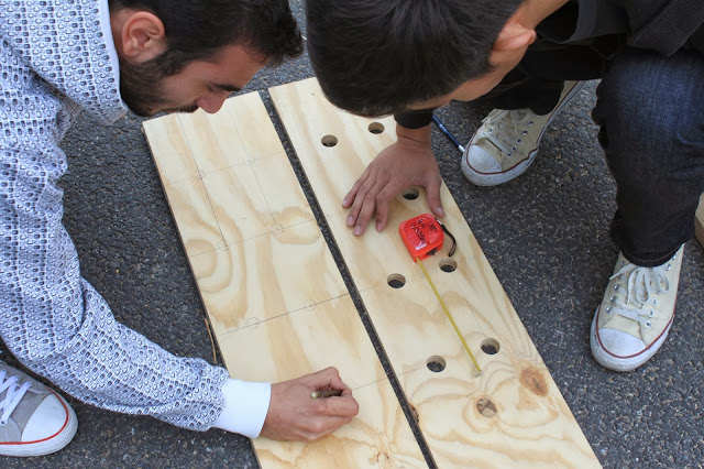
Today we concentrated on cutting all the pieces and drilling all the holes to have them all ready for the assembly. We took measurements for the partition of the beam and figured out a new and faster way to do the holes on them. Instead of marking each one of them separately we decided to mark one and drill through all the plywood panels in one go. That boosted our productivity and saved us from a lot of wasted time on marking and labeling which proved to be inefficient anyway.

Making sure the panels are strengthened on the right spots


The problem we were facing in the previous days was that the panels were marked as individual pieces and because of the manual marking and human error tolerance we kept ending up with holes that wouldn't match with each other. Therefore, we used clamps to have all the panels aligned and then drilled the holes through all the layers.
While all the drilling was happening, the dowels were being cut in specific sizes for the interlocks between the beams and posts and thus we would ideally have all the pieces ready for assembly tomorrow.

Cutting the dowels to use as interlocks

Wednesday, 2 October 2013

Day 8: Ready, steady, Go

Continuing our work from yesterday, we started by making measurements and cutting the little pieces that will act as bracing between the plywood post. In the spirit of making the whole thing deployable anywhere, we decided not to screw these pieces to the post but instead to use the same method of the dowels to lock them in place.

Smaller plywood pieces to brace the post in between

Using dowels yet again for the inner brace
Carrying the post is relatively easy (according to Giannis who carried it first)
While that was going on we tested out the second post to complete the frame and questioned its structural integrity, rigidness, flexibility and overall finesse. Lifting and moving the post in place was relatively easy which indicated its easy deployability while at the same time locking it in place was none the harder.


Locking the post and the beam in place

Free standing structure!

At the moment we have experimented with two different types of posts. The one at the front is timber-ply-timber-ply-timber-ply-timber while the one at the back is timber-ply-ply-ply-ply-timber. We've explored the structural integrity in each case and the materials required as we are shorthanded on this aspect of our project.

For more efficiency we decided to split in groups: Group 1 would stay on the small braces and work out calculations and depths of the holes for the interlocks, Group 2 would cut and mark the next plywood panel in order for it to be assembled as a new post tomorrow and Group 3 would work on a new variation of the beam that we wanted to test out. This new beam will consist of 2 timber panels on the outer side while braced with small pieces of plywood.

Group 1: Bracing the inner sides of the column

Cutting and marking the next plywood panel

Creating a new variation of a beam
Our design concept is to criss cross at least two frames thus creating a space underneath and in order to do that we need to lock the two beams together. Our approach to this matter involves creating 2 mirrored notches for the beams to interlock.

Notches on the first beam

Notches on the second beam

Mirrored notches on the beam to allow flexibility to interlock with the other beams
Everything seems assembled and ready to transform our conceptual lines into reality. It seemed rather clear that the second beam was too heavy and risky to get the green light for our construction line but everything else is rigid and stable. Even though we still miss two posts for the load to be transferred correctly, the structure is quite solid as a unit and we are very optimistic that when the other posts are in place as well it will be much stronger.


Alex was there as well to give as some tips and advice concerning our future steps on the project for tomorrow. We need to replace the second beam with one made of plywood which will be much lighter and will have more potential to support a roof. A base is needed of a size at least the footprint of the column but that is something we left on the side for tomorrow. In the spirit of learning from our mistakes we covered all our wood pieces with a large fabric and the acrylic panels we have as spare materials as we already lost some pieces to the rain.

Shhhh.... She's sleeping

Tuesday, 1 October 2013

Day 7: The first post rises

Today we started early by cutting the plywood pieces off the panels into equal ones. One of the problems we encountered was that the measurements of the panel were exactly divided into 6 equal pieces but we didn't take into consideration the width of the saw blade which was 2mm and eventually cost us 1 piece on each panel. Truth be told, the edges of the plywood were not usable anyway so there was n drawback in the whole process.

Cutting the plywood panels on the vertical saw
1 of the 6 pieces is in such a bad condition that we can't use it anyway
We made some calculations and drew the first lines on the timber only to discover that we would require dowels to complete our design. Therefore, we decided that two people could go to B&Q for some dowels and the rest of the group could stay back at uni to start drilling the holes.

Sketching our plans for the correct measurements of the holes

Alignment is crucial 

We used 28mm holes and dowels to give more structural integrity to the module but we found out the hard way that when you manually cut and drill timber pieces and expect them to perfectly stack on each other one can never be completely sure that they will. Even less than 1mm difference in between the holes proved to be disastrous for assembling the pieces together. 
Or module rises for the first time


The angle of entry of the dowel plays an important role in the assembly process and if the holes are not perfectly aligned it can prove to be a big problem.
For tomorrow we need to reflect more on the mistakes of the present and think of an alternative way to make the assembling process easier and more achievable. Our first course of action is to drill a 30mm hole still using the 28mm dowel thus sacrificing structural integrity and risking of making the post a bit flimsy. 

Monday, 30 September 2013

Day 6: Learning through making

Starting early in the morning we split in 2 groups, one started to make the lap joint that we had been working on during the weekend and the other group stayed in the Archive room to fill Alex in on our progress so far. Through the meeting we came to the realization that the frame we had already designed was a bit flimsy but had the potential to become stronger and sturdier as a laminate piece. Instead of using the timber posts already in our disposal we came up with the idea of laminating plywood panels together to create a better base and junction in terms of flexibility and load bearing.

Getting measurements for the cutting lines on the timber panels (Group 1)
Initial idea of junction between posts and beam
Morning meeting with Alex (Group 2)

Confronting our problems through sketchin


We grouped up as a single unit to discuss this idea and came up with sketches and different scenarios about  how we  could   use  the  plywood  panels  to create our  whole  design concept. First  idea  based on this theory was to  have  4 plywood  panels as  a base and beam  ( 2 on each side ) and in the middle there would be  an ''L''  shaped   plywood   laminate that  would  act  as  a  brace  between  the 2  sides. Apart from that bracing there would also be smaller pieces alongside the length of the beam and the post to hold it together.


We talked this idea over again with Alex and decided to go for a prototype that would be a small variation of the one we thought of. This version consists  of  3 pieces of plywood not put  together but  braced with  each other with timber in between creating a three layered sandwich that would  make the frame even  stronger. In my  personal  opinion  we  weren't  quite convinced  it would work out  but through constantly  improving the design while cutting the pieces, it turned out to be a really successful design process.

Presenting our model of the plywood panel idea

Cutting the plywood panel in identical pieces


Measuring and  drawing  precise  lines 
is essential to this part of the project as we are trying to create a prototype of the base and middle part of the post to get a sense of what is working and what is not.
Cutting the strips of plywood in 3 identical pieces

Experimenting with the possible variations of junction

Experimenting with different types of wood for bracing


Ply-timber-ply-timber-ply
The composition of our module

On the middle piece (picture below)
we create some kind of socket so it
can interlock with other pieces
vertically.

Cutting holes on the small bracing pieces for the pegs to go through

Inner brace for the base module


It seems  like  we cant  create a  lap
joint using plywood since the pieces
that the ply  consists of break  apart
when cut. Instead, we created a peg system which locks all the pieces together.
Composition of the base module

Our first prototype is ready

Workshop 7 after a long and hard Monday


 For the base we came up with a peg system that increases the total length of each post which is useful in the case of slanted ground. Through the creation of this part, we came across another problem that still needs to be addressed which is the base unit. A solid base is still required for the post to fit in and lock in place for more stability.
 If there is one thing to take away from today is that through the actual making of the prototype we spotted numerous new problems and found solution for previous ones that puzzled us. Coming up on Tuesday the construction of the 1:1 module which seems like a relatively easy thing to do, now that we are equipped with all the new experiences from today. An early morning meeting is scheduled for tomorrow at 10.00 am to work out the issues that still trouble us and get our hands on the 1:1 module.